
Views: 0 Author: Site Editor Publish Time: 2026-08-06 Origin: Site


Coating porosity destroys industrial components. Microscopic voids let corrosive fluids attack the base metal. This sub-surface oxidation causes blistering, accelerated wear, galling, fretting, and catastrophic part failure. You lose money on premature replacements and unplanned downtime. A single failed gate valve in a refinery can halt production for days, costing hundreds of thousands of dollars. You need a better thermal spray method. High Velocity Oxygen Fuel technology fixes this. It builds dense, impenetrable surface barriers. By prioritizing kinetic energy over thermal energy, modern HVOF Spray Equipment shoots powder at supersonic speeds. Particles flatten and interlock on impact. This eliminates the voids and trapped gases common in high-temperature melting methods.
HVOF spray equipment utilizes supersonic particle velocities to create dense, mechanical bonds, consistently achieving porosity levels below 1% (often under 0.5%).
Unlike traditional plasma or arc spraying, HVOF operates at relatively low substrate temperatures (typically under 300°F), preventing thermal distortion and metallurgical degradation.
Achieving a low porosity HVOF coating requires precise calibration of equipment variables, specifically oxygen-fuel flow rates and standoff distance.
Evaluating HVOF systems requires balancing upfront equipment and operational costs against the long-term ROI of extended component lifecycles, slower wear rates, and superior corrosion resistance in harsh environments.
Instead of melting powder into a liquid, we use extreme pressure and gas dynamics. Oxygen mixes with fuel inside the combustion chamber and ignites. The exhaust gas blasts through a converging-diverging Laval nozzle. This accelerates the gas stream past Mach 4. We inject semi-molten powder, typically sized between 15 and 45 microns, into this stream. Depending on the gun design, we use radial or axial injection to get the powder into the center of the flame. The particles accelerate toward the target.
When they hit the substrate, kinetic energy turns into mechanical deformation. The particles smash flat into microscopic splats. They conform tightly to the surface and to each other. You get a dense, interlocking microstructure without gaps. Supersonic speeds give you a time-in-flight advantage. Particles spend milliseconds in the hot plume. They do not fully melt, and they do not oxidize in mid-air. Mid-air oxidation forms hard shells that shatter on impact, causing voids. High velocity prevents this.
Plasma spraying does the opposite. It uses massive heat to melt the powder completely. Slow-moving liquid droplets absorb gases. When they hit the part and freeze, those trapped gases form spherical voids. You lose compressive strength and leave the part vulnerable to impact damage.
Industry specs demand strict benchmarks for severe service environments. A Low Porosity HVOF Coating must test under 1% total porosity. Aerospace and subsea oil extraction applications push this under 0.5%. Verifying these numbers requires precise metallographic preparation. We cut sample coupons, mount them in epoxy, polish them to a mirror finish, and analyze them under an optical microscope using image analysis software. Hitting these numbers completely changes how a part performs.
Low porosity directly increases macro-hardness and slows wear rates. We see this constantly with tungsten carbide and chromium carbide. A dense metallic binder matrix locks the hard carbide grains in place. The structure fights off abrasive and erosive forces. If the matrix has voids, abrasive materials rip the carbide grains out. The surface degrades fast.
A dense structure blocks corrosive pathways. Corrosive media cannot reach the base metal. The extreme impact velocity also drives particles deep into the grit-blasted anchor profile. This mechanical interlock delivers massive bond strength. The layer stays put under heavy mechanical loads, resisting spalling and flaking even when subjected to severe point loading.
Standoff distance is the gap between the spray gun nozzle and the part. You must control this gap to manage kinetic energy and heat. Particles need exact milliseconds to soften and accelerate. For gas-fueled systems, this distance typically ranges from 8 to 12 inches. For higher-velocity liquid systems, it might extend to 15 inches. Operators monitor the shock diamonds visible in the supersonic plume to gauge flame dynamics.
If you shorten the standoff distance too much, particles do not absorb enough heat. They hit the part solid. Solid particles bounce off or embed poorly. You get a rough surface and massive voids. A short gap also causes particles to collide in mid-air, wrecking the spray plume.
If you extend the standoff distance too far, aerodynamic drag slows the particles down. They cool off. They lose the kinetic energy needed for severe plastic deformation. They stack loosely. You end up with poor splat formation, high porosity, and weak bonds.
You have to find the moderate sweet spot. The optimal distance maximizes impact right when particles reach optimal plasticity. You calibrate this based on the powder's particle size distribution. You program the robot to hold this exact gap across every contour of the part, ensuring the gun stays perfectly perpendicular to the surface.
The oxygen-fuel mixture controls the temperature and velocity of the exhaust jet. Different fuels burn at different temperatures. Propylene burns hotter than hydrogen, changing the thermal input to the powder. A fuel-rich mix burns cooler. An oxygen-rich mix burns hotter. You need the exact stoichiometric balance to soften the powder without vaporizing it.
Excess oxygen ruins coating density. Uncombusted oxygen reacts with the hot powder in flight. This creates brittle oxide inclusions. When oxidized particles hit the part, they do not deform. They create rigid boundaries. Adjacent splats cannot fuse. Structural integrity drops.
You control this with mass flow controllers. These devices maintain precise gas ratios even if supply pressures or shop temperatures fluctuate. A minor drift in gas flow changes the flame chemistry immediately. Porosity spikes. You must calibrate these controllers regularly. We also monitor the powder feeder closely. Modern feeders use weigh-scale feedback to ensure a constant mass flow of powder into the gun. If the powder feed rate drops, the flame becomes too hot for the remaining particles, over-melting them and increasing porosity.
The flame is hot, but the part must stay cool. You must keep substrate temperatures below 300°F during the entire spray process. We monitor this in real-time using infrared pyrometers or surface thermocouples. If the part gets hotter, you risk altering the base metal's mechanical properties. Heat-treated alloys can anneal, warp, or lose tensile strength.
We manage heat with aggressive cooling setups. We mount compressed air jets directly to the robotic arm. They trail the spray plume and instantly cool the fresh layer. For thin-walled parts, we use liquid CO2 cooling systems to pull heat out fast without contaminating the surface.
Controlling heat protects the coating itself. If the part overheats and expands, it will contract violently when it cools. This contraction creates severe residual tensile stress in the coating. High tensile stress causes micro-cracking. Under a microscope, these cracks look like porosity and act as failure points. Proper temperature management keeps the coating in a state of neutral or slight compressive stress, which actually improves fatigue life.
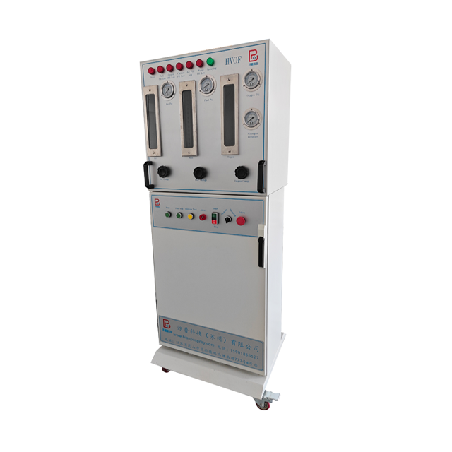
Certain environments demand high-velocity impact coatings. Aerospace landing gear takes massive impact loads and fights atmospheric corrosion during flight cycles. Oil and gas gate valves handle extreme pressure, abrasive sand, and corrosive hydrogen sulfide in subsea wells. Mud motor rotors in drilling operations endure severe abrasion from drilling fluids. Kaplan turbine blades in hydro plants face constant cavitation and silt erosion. Standard thermal sprays fail here.
You need strict evaluation metrics. Bond strength must exceed 10,000 PSI in standardized pull tests, often breaking the epoxy before the coating fails. Micro-hardness tests on the HV300 scale verify the density of the carbide matrix. Salt-spray testing must show thousands of hours of protection. The low-porosity barrier blocks electrolyte penetration, preventing galvanic corrosion between the coating and the substrate.
| Evaluation Metric | Industry Standard Target | Impact of High Porosity |
|---|---|---|
| Porosity Level | < 1% (Often < 0.5%) | Allows corrosive ingress and accelerates wear. |
| Bond Strength | > 10,000 PSI | Causes delamination and catastrophic peeling. |
| Micro-Hardness | > 1000 HV300 (for Tungsten Carbide) | Reduces abrasion resistance and shortens lifespan. |
| Substrate Temperature | Maintained < 300°F | Induces thermal distortion and residual stress. |
Manual application does not work for high-performance coatings. A human cannot hold a perfectly consistent standoff distance or traverse speed across a complex part. Speed and distance variations change the heat input and kinetic impact instantly.
You need automated manipulation. Robotic arms execute precise tool paths. Operators use teach pendants or offline programming software to map the exact geometry of the component. The spray gun stays at the exact optimal distance and angle. This consistency controls porosity. Whether you spray a flat plate, a cylindrical pump shaft, or a complex valve internal, automation ensures every inch gets identical kinetic and thermal energy. The robot also controls the step size—the distance the gun moves down the part after each pass. A precise step size ensures uniform coating thickness and prevents localized heat buildup.
You have to choose your combustion chemistry. High-Velocity Air Fuel (HVAF) and gas-fueled systems use hydrogen, propylene, or propane. They offer excellent control, lower operating costs, and produce dense coatings for most industrial jobs. Gas systems are generally easier to maintain and require less complex cooling infrastructure.
Liquid-fueled systems use kerosene. They run at higher combustion chamber pressures. Liquid systems generate higher particle velocities. This extra kinetic energy creates denser, lower-porosity coatings for extreme wear environments. But kerosene systems are complex. They require heavy-duty pump infrastructure to deliver fuel at high pressure. The extreme heat generated by liquid combustion demands robust water-cooling systems for the gun. Operators must perform frequent combustion chamber maintenance to clear carbon buildup, which can disrupt the flame geometry and cause spitting.
Buying good hardware does not guarantee good coatings. High-velocity spray systems drift. Minor changes in cooling water temperature, ambient humidity, or powder feed rates alter the flame dynamics. These minor drifts compound. Porosity spikes and bond strength drops.
You mitigate this with closed-loop control systems. They monitor and adjust gas flows in real-time, compensating for pressure drops in the supply lines. You also need rigorous operator training. Operators must understand thermal diagnostics, flow rate monitoring, and the visual cues of a bad spray plume. They need to know how to read the shock diamonds and identify when the nozzle is wearing out. A worn nozzle loses its converging-diverging profile, dropping the gas velocity and instantly increasing coating porosity.
Great equipment cannot fix bad surface prep. This process relies entirely on a mechanical bond. The substrate needs an aggressive anchor profile for the splats to grip. Grit blasting is mandatory.
Improper profiling causes delamination. You must blast the surface to a white-metal finish using sharp, angular aluminum oxide grit, typically 24-mesh or 36-mesh. This creates a jagged microscopic topography with a surface roughness of 3 to 4 mils Ra. If you use dull grit, it peens the surface instead of cutting it. If you leave oil or moisture on the part, the high-velocity particles will flatten out but fail to interlock. The coating will peel off under load. Operators must spray the part immediately after blasting to prevent flash rusting. Any oxidation on the blasted surface acts as a bond breaker.
Upgrading to supersonic thermal spray technology requires high capital expenditure. You have to buy the spray gun, the console, specialized acoustic booths to handle 130-decibel noise, and heavy-duty dust collection systems for the overspray. You also need a robust chiller to keep the gun from melting.
You justify the cost through operational efficiency. You recoup the investment by drastically reducing component replacement frequency. Parts that lasted months now run for years because wear rates drop. A refinery that avoids a single unplanned shutdown pays for the entire spray cell. Transitioning to this technology also eliminates the environmental compliance costs of hard chrome plating. Replacing hexavalent chromium baths with mechanically applied carbide layers removes toxic waste streams, eliminates the need for expensive exhaust scrubbers, and simplifies facility permitting.
High-velocity thermal spray technology is the definitive solution for severe wear and corrosion resistance. Extreme kinetic impact mechanically forces porosity below the 1% threshold. This creates an impenetrable barrier that extends component lifecycles in harsh environments. Moving from thermal melting to kinetic deformation changes the durability of the applied layer.
Prioritize equipment vendors that offer robust mass flow control and automated robotic integration. Consistent parameter management guarantees repeatable density. Seek vendors who provide comprehensive parameter development support for specific carbide powders and complex geometries.
Before committing to full-scale equipment procurement, take the following actionable steps:
Conduct a localized pilot test using your specific operational components to evaluate real-world application challenges.
Request metallurgical cross-sections of sample coupons sprayed with the proposed equipment to visually verify porosity levels and splat cohesion.
Perform standardized pull tests on these coupons to confirm the mechanical bond strength meets your engineering requirements.
Evaluate your facility's infrastructure to ensure adequate space and power for acoustic enclosures, chillers, and dust collection systems.
A: High-performance coatings applied via high-velocity equipment typically exhibit porosity levels below 1%. In premium aerospace and oil and gas applications, industry standards often demand porosity under 0.5%. This extremely dense structure eliminates voids, blocks corrosive ingress, and contributes directly to significantly slower wear rates under heavy abrasion.
A: Maintaining a moderate standoff distance is essential. If the distance is too short, particles lack heating time and bounce off or collide in mid-air, causing roughness. If the distance is too long, aerodynamic drag slows the particles, reducing their kinetic impact. Both extremes result in poor splat deformation and increased voids.
A: Plasma spray relies on high heat and low velocity, melting particles completely. This traps gases and creates porous, weaker structures upon solidification. High-velocity systems use low heat and extreme kinetic energy. Particles remain semi-molten and smash into the substrate at supersonic speeds, creating tightly interlocking, highly dense mechanical bonds.
A: Substrate temperatures are strictly managed and typically kept below 300°F during the entire application process. Operators use compressed air jets or liquid CO2 cooling to extract heat rapidly. This low-temperature approach prevents thermal distortion, residual tensile stress, and metallurgical changes to the base metal.
A: Oxygen flow rates dictate combustion stoichiometry. A precise balance is required to achieve optimal flame velocity and temperature. Excess oxygen in the plume reacts with the flying powder, creating brittle oxide inclusions. These oxidized particles shatter upon impact rather than deforming, which severely compromises coating density and strength.
A: Yes. Applying tungsten carbide via high-velocity equipment is the primary environmentally compliant alternative to hard chrome plating. It eliminates the toxic hexavalent chromium process while offering superior density, higher macro-hardness, and significantly better wear characteristics for hydraulic cylinders, landing gear, and industrial rotors.


