
Views: 0 Author: Site Editor Publish Time: 2026-08-28 Origin: Site


High-Velocity Oxygen Fuel (HVOF) thermal spraying achieves industry-leading coating density and bond strength. These outcomes rely entirely on the precise synchronization of highly pressurized gases, volatile fuels, and extreme thermodynamics. The process operates under severe conditions, pushing materials to their physical limits to produce wear-resistant and corrosion-resistant surfaces.
For engineering and procurement teams, evaluating these complex thermal spray setups presents a significant challenge. Misjudging the specifications of individual components—such as cooling capacities, mass flow controllers, or powder delivery mechanisms—leads to inconsistent coating quality, frequent equipment downtime, and severe safety risks. A minor fluctuation in gas pressure or water temperature can compromise the metallurgical integrity of the final coating.
Selecting the right system requires a granular understanding of its architecture. This guide deconstructs the primary components of industrial HVOF Spray Equipment, providing a framework to evaluate hardware capabilities, facility requirements, and long-term operational reliability.
Fuel Type Dictates Architecture: The choice between gas-fuel (HVOF-GF) and liquid-fuel (HVOF-LF) systems fundamentally alters the required gas management consoles, pump configurations, and cooling infrastructure.
The Gun is the Critical Path: The internal geometry of the HVOF spray gun system—specifically the combustion chamber and converging-diverging nozzle—directly controls particle velocity and coating porosity.
Precision Relies on Peripherals: Consistent coating quality is governed not just by the gun, but by the accuracy of closed-loop mass flow controllers (MFCs) and gravimetric powder feeders.
Infrastructure is Non-Negotiable: Facility planning must account for mandatory facility integrations, including high-capacity industrial chillers, acoustical enclosures, and specialized dust collection systems.
The primary goal of an HVOF system is to generate a supersonic gas jet with controlled thermal output. This jet melts and accelerates powder particles toward a substrate without degrading their metallurgical properties. Preventing issues like carbide decarburization requires strict control over the combustion environment. The system must balance kinetic energy and thermal energy perfectly to achieve the desired splat morphology upon impact.
HVOF systems are categorized by their fuel source. Gas-fueled systems (HVOF-GF) utilize propane, hydrogen, propylene, or natural gas. These systems are highly versatile and excel at applying metallic alloys and specific cermets. They operate at slightly lower combustion pressures than their liquid counterparts, making them easier to manage in terms of pumping and fluid delivery. On the shop floor, gas systems are often favored for their rapid startup sequences and broad parameter windows.
Liquid-fueled systems (HVOF-LF) utilize kerosene or aviation fuel. These systems generate significantly higher combustion pressures and require robust, high-pressure liquid pumps to atomize the fuel before ignition. The higher pressure translates to higher gas velocities, producing extremely dense coatings. HVOF-LF is the preferred choice for applying thick, dense tungsten carbide coatings in heavy industrial applications like oil and gas drilling components.
HVOF operates on an inverse relationship between temperature and velocity when compared to traditional plasma spray. While plasma spray generates extreme temperatures with relatively low particle velocities, HVOF generates moderate temperatures with extreme supersonic velocities. This kinetic-heavy approach forces particles to impact the substrate with massive physical force, mechanically interlocking them into the surface.
System components must maintain this precise equilibrium. If the temperature is too high, the powder particles may vaporize or undergo detrimental phase changes. If the velocity is too low, the particles will not deform sufficiently upon impact, leading to high porosity. Properly calibrated equipment achieves less than 1% porosity in coatings across various materials, including metals, cermets, and specialized ceramics.
| Feature | Gas-Fuel (HVOF-GF) | Liquid-Fuel (HVOF-LF) |
|---|---|---|
| Typical Fuels | Propane, Hydrogen, Natural Gas | Kerosene, Aviation Fuel |
| Combustion Pressure | Moderate (60 - 120 PSI) | High (100 - 200+ PSI) |
| Particle Velocity | High (Mach 1.5 - Mach 2) | Extremely High (Mach 2 - Mach 3) |
| Primary Applications | Metallic alloys, thin cermets | Thick, dense tungsten carbides |
| Pumping Infrastructure | Standard gas regulation panels | High-pressure liquid atomization pumps |
The HVOF Spray Gun System serves as the focal point of the entire operation. This is where fuel, oxygen, and engineered powder intersect under extreme pressure. The gun's internal geometry dictates the efficiency of the combustion and the acceleration of the powder particles. Every millimeter of the internal design impacts the final coating quality.
The combustion chamber is engineered to withstand continuous high-pressure detonation. It must contain the violent reaction of oxygen and fuel while directing the expanding gases forward. Materials used in the chamber, typically oxygen-free high thermal conductivity copper, must resist thermal fatigue and oxidation over thousands of operating hours.
Ignition methods vary between manufacturers. Some utilize high-voltage spark plugs directly within the chamber, while others rely on external pilot flames. Regardless of the ignition method, mandatory safety interlocks are integrated into the design. Flashback arrestors are critical components that prevent the combustion flame from traveling backward into the gas supply lines, which could cause catastrophic explosions.
The acceleration of exhaust gases relies on the physics of the converging-diverging nozzle, commonly known as a De Laval nozzle. As the high-pressure combustion gases pass through the narrow throat of the nozzle, they reach the speed of sound (Mach 1). As the nozzle diverges and expands, the gases accelerate further to supersonic speeds, often reaching Mach 2 to Mach 3.
Nozzle length and internal diameter directly impact particle dwell time. A longer nozzle allows particles more time to absorb heat and accelerate, which is beneficial for materials with higher melting points. Barrel materials are typically lined with tungsten carbide or other refractory metals to resist the severe abrasive wear caused by the high-velocity powder stream. Operators must monitor these liners closely, as internal wear alters the gas dynamics and degrades coating density.
Powder must be injected into the high-velocity gas stream with absolute precision. Axial injection feeds the powder directly through the center of the combustion chamber. This method ensures the particles travel through the hottest part of the flame, maximizing thermal transfer. However, it requires higher carrier gas pressures to overcome the combustion pressure.
Radial injection feeds the powder downstream of the combustion zone, typically into the diverging section of the nozzle. This approach reduces the thermal load on the particles, which is advantageous for temperature-sensitive materials like certain carbides. Injection positioning heavily influences the risk of nozzle buildup, commonly referred to as spitting, where melted particles adhere to the inner walls of the barrel.
| Injection Type | Injection Location | Thermal Load on Powder | Risk of Nozzle Buildup | Best Suited For |
|---|---|---|---|---|
| Axial | Center of combustion chamber | High (passes through primary flame) | Moderate to High | High melting point alloys, robust metals |
| Radial | Downstream in the diverging nozzle | Lower (bypasses primary flame core) | Low | Temperature-sensitive carbides, cermets |
The thermal output of the combustion process is immense. Without active cooling, the gun would melt within seconds. Internal water-cooling channels are integrated directly into the gun body and nozzle assembly. These cooling jackets circulate high-pressure water to extract heat, preventing structural failure and maintaining the dimensional stability of the nozzle during prolonged operation. The design of these micro-channels ensures turbulent water flow, which maximizes heat transfer away from the copper components.
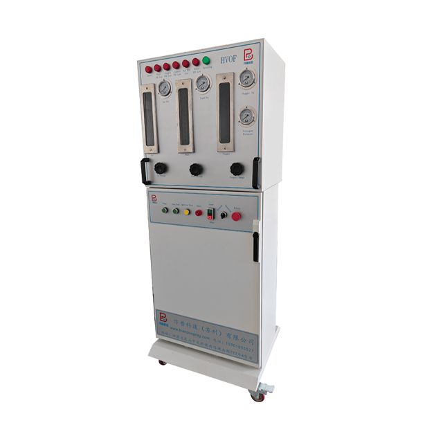
The control console functions as the brain of the equipment. It governs the precise delivery of all consumables and ensures absolute process repeatability. Evaluating the control console requires looking past the user interface and examining the underlying fluid dynamics hardware. A robust console guarantees that the parameters set by the engineer are exactly what the gun receives.
Maintaining exact stoichiometric ratios between oxygen and fuel is critical for consistent combustion. Traditional rotameters rely on mechanical floats and are highly susceptible to backpressure and temperature fluctuations. Modern industrial systems utilize closed-loop Mass Flow Controllers (MFCs).
MFCs measure the actual mass of the gas passing through the line, regardless of pressure or temperature variations. They continuously adjust internal proportional valves to maintain the exact setpoint programmed by the operator. This closed-loop feedback compensates for upstream pressure fluctuations from bulk tanks, preventing flameouts, pulsing, or coating inconsistencies. If a bulk oxygen tank experiences a sudden pressure drop, the MFC instantly opens its valve wider to maintain the required mass flow.
Powder cannot flow from the feeder to the gun on its own; it requires a carrier gas. Inert gases are used to transport the powder. The carrier gas serves a dual purpose: it provides the pneumatic force for transport and shrouds the powder particles to prevent premature oxidation before they enter the combustion zone.
Nitrogen: The most common and cost-effective carrier gas, suitable for the vast majority of carbide and metallic applications.
Argon: Used when spraying highly reactive materials like titanium alloys, providing a completely inert shroud.
Helium: Occasionally used for its high thermal conductivity, though its high cost limits its application to highly specialized aerospace coatings.
Manual control of gas flows and ignition sequences is obsolete in modern industrial applications. Programmable Logic Controllers (PLCs) handle all automation tasks. They manage recipe storage, ensuring that specific parameter sets can be recalled instantly for repeat production runs. This eliminates operator error during setup.
PLCs also control automated startup and shutdown sequences, purging lines with inert gas to ensure safety. For industries with strict quality control standards, such as aerospace or medical device manufacturing, PLCs integrate with SCADA systems to provide real-time data logging. This creates a permanent digital record of every parameter during the coating process, which is a strict requirement for Nadcap compliance.
Delivering high-density powders into a high-pressure combustion stream requires specialized mechanical systems. Unlike other thermal spray processes that can utilize wire or rod forms, this process relies exclusively on precisely engineered powder morphologies. The powder feeder must deliver a continuous, non-pulsing stream of material.
Feeders must be calibrated to handle diverse coating materials. The physical properties of these powders vary drastically. Heavy Tungsten Carbide-Cobalt powders flow differently than lighter metallic alloys like Inconel or stainless steel. The feeder mechanism must accommodate different particle size distributions, typically ranging from 15 to 45 microns, without clogging or bridging. The internal discs and suction ports are often swapped out depending on the specific powder morphology being sprayed.
Volumetric feeders operate based on RPM. A rotating disc or wheel picks up a specific volume of powder per revolution. While reliable, volumetric feeders cannot account for variations in powder density or flowability. If a batch of powder is slightly denser, the actual mass delivered to the gun will increase, altering the coating properties.
Gravimetric feeders operate on a weight-loss basis. The entire hopper is mounted on precision load cells. The control system monitors the exact weight of the powder leaving the hopper in real-time and adjusts the mechanical feed rate to maintain a constant mass flow. Gravimetric feeding is critical for strict quality control and continuous, long-duration production runs where parameter drift is unacceptable.
| Feeder Type | Operating Principle | Density Compensation | Ideal Application |
|---|---|---|---|
| Volumetric | RPM-based volume displacement | None (assumes constant density) | Short runs, less critical dimensional tolerances |
| Gravimetric | Real-time weight-loss monitoring | Automatic (adjusts RPM to maintain mass) | Aerospace, long continuous runs, strict QC |
Powder hoppers are highly engineered pressure vessels. They must be pressurized with the carrier gas to push the powder toward the gun. To prevent powder bridging—where particles interlock and stop flowing—hoppers utilize mechanical stirrers and fluidization techniques.
Fluidization introduces carrier gas through a porous plate at the bottom of the hopper, lifting and separating the powder particles. Additionally, hoppers are often equipped with heater jackets. Heating the powder removes residual moisture, which is a primary cause of agglomeration and inconsistent flow rates. A dry powder flows predictably, ensuring a stable feed rate into the combustion chamber.
The massive thermal output of the combustion process demands aggressive thermal management. The infrastructure required to cool the equipment is often larger than the control consoles themselves. Inadequate cooling leads to immediate catastrophic failure of the gun components.
Industrial guns require dedicated refrigerated chillers. The typical cooling capacity required ranges from 30kW to over 100kW, depending on the specific gun design and fuel type. Liquid-fueled systems generally require higher cooling capacities due to their elevated combustion temperatures and pressures.
Many facilities utilize dual-circuit chillers. One high-capacity circuit is dedicated entirely to the spray gun, while a secondary, lower-capacity circuit cools the power supplies, liquid fuel pumps, and control cabinets. This separation ensures that pressure drops in the cabinet cooling lines do not starve the gun of critical water flow.
Cooling water must be delivered at specific flow rates and pressures to overcome the resistance of the micro-cooling channels inside the gun. Standard tap water is strictly prohibited. Deionized or highly filtered reverse-osmosis water is required.
Using untreated water causes rapid scaling inside the hot copper components of the gun. Scale acts as an insulator, preventing heat transfer and causing the nozzle to melt. Furthermore, strict control of water conductivity prevents galvanic corrosion between the dissimilar metals used in the gun assembly and the cooling loop.
To maintain the cooling system, operators follow a strict maintenance protocol:
Verify the water conductivity levels daily to ensure they remain below the OEM specified micro-siemens threshold.
Inspect the inline particulate filters weekly and replace them if pressure drops are detected across the filter housing.
Check the glycol concentration levels monthly if the chiller is located in an environment susceptible to freezing temperatures.
Perform a complete system flush and replace the deionized water annually to prevent biological growth in the reservoir.
Manual operation of this equipment is virtually impossible and highly dangerous. The extreme kinetic energy, noise, and thermal output necessitate fully automated handling. Robotic integration ensures consistency, safety, and scalability in production environments.
Six-axis industrial robots are the standard for manipulating the spray gun. They maintain precise standoff distances, typically between 6 to 15 inches, depending on the nozzle configuration and material. The robot also controls the traverse speed, ensuring uniform coating thickness across complex geometries.
Consistent traverse speed is vital. If the gun moves too slowly, localized substrate overheating occurs, leading to thermal distortion or metallurgical damage to the base part. If the gun moves too quickly, the coating will be too thin, requiring excessive passes and wasting expensive powder. Programmers set the Tool Center Point (TCP) speed to guarantee the gun moves at the exact required velocity regardless of the robot's joint articulation.
While the robot moves the gun, synchronized part manipulation equipment moves the substrate. Heavy-duty lathes are required for coating cylindrical components like hydraulic cylinders, pump shafts, and landing gear struts. Turntables are utilized for flat or complex three-dimensional parts.
The rotation speed of the lathe or turntable is mathematically synchronized with the robot's traverse speed to create a precise raster pattern. This synchronization guarantees an even overlap of the spray passes, preventing weak spots or porosity in the final coating. The step-over distance is calculated based on the spray plume's footprint.
Automated coating cells rarely operate in isolation. They often integrate or operate in tandem with automated grit-blasting equipment. Achieving a specific surface roughness profile is a mandatory precursor for mechanical bonding. The substrate must be blasted with aluminum oxide or chilled iron grit to create an anchor pattern before the coating is applied. Without this rough profile, the supersonic particles will simply bounce off the smooth metal surface.
Installing this technology requires significant facility modifications. The environmental and safety infrastructure surrounding the equipment is mandatory for regulatory compliance and risk mitigation. Operators must be protected from extreme noise, hazardous dust, and high-pressure gases.
The supersonic exhaust jet generates extreme noise levels, often exceeding 130 decibels (dB). This is equivalent to standing next to a military jet engine during takeoff. Engineered soundproof booths are required to contain the noise and protect the hearing of facility personnel.
These acoustical enclosures are constructed with specialized sound-absorbing panels and heavy-duty acoustic doors. The doors are equipped with safety interlocks; if a door is opened during operation, the PLC instantly terminates the combustion sequence to protect personnel from both the noise and the kinetic blast.
Overspray is inevitable in any thermal spray process. The fine powder particles that do not adhere to the substrate must be safely extracted from the booth. Depending on the materials being sprayed, specialized dust collection systems are required to meet NFPA standards for combustible dusts.
When spraying hazardous materials like hexavalent chromium alternatives, nickel alloys, or cobalt-bound carbides, wet scrubbers or HEPA-filtered dry dust collectors are mandatory. Wet scrubbers draw the dust-laden air through a water curtain, trapping the combustible or toxic particles in a sludge for safe disposal. Proper ventilation also maintains negative pressure inside the booth, preventing dust from escaping into the wider facility.
The volume of gases consumed requires bulk storage solutions. Facilities must install high-pressure oxygen bulk tanks or liquid oxygen (LOX) vaporizers. Liquid fuel storage requires rated tanks with secondary containment to prevent environmental contamination.
Active gas leak detection sensors must be installed inside the spray booth and near the gas mixing consoles. Blast-resistant gas routing and heavy-duty stainless steel piping are used to transport gases from the storage yard to the control console, adhering strictly to NFPA and OSHA safety standards. Flashback arrestors are installed at multiple points along the gas delivery lines.
Comparing different OEM systems requires looking at operational efficiency, hardware modularity, and vendor support. A framework based on these factors provides a clearer picture of the equipment's true value on the production floor.
Production requirements change over time. Systems that offer high modularity provide significant advantages. Evaluate control consoles that allow for interchangeable guns. For example, a facility may need to switch between a standard outer diameter (OD) gun and a specialized internal diameter (ID) gun for coating the inside of pipes or cylinders.
A modular control architecture allows the operator to swap the hardware and select a different software profile on the PLC without requiring a completely separate gas management console. This flexibility maximizes the utility of the initial investment and allows the facility to bid on a wider variety of coating contracts.
Even the most robust systems require regular maintenance and replacement parts. Selecting vendors with robust domestic supply chains for critical wear parts is essential. If a proprietary nozzle or mass flow controller fails, waiting weeks for international shipping will paralyze production.
Responsive technical support is equally important. OEMs that offer remote diagnostics, where engineers can securely log into the PLC to troubleshoot fault codes, drastically minimize production downtime and reduce the need for expensive on-site service calls. Look for systems built with non-proprietary, off-the-shelf PLC components (like standard Siemens or Allen-Bradley modules) to ensure long-term serviceability.
An HVOF system is only as reliable as its weakest component. A high-end spray gun cannot compensate for poor mass flow control, inadequate cooling, or inconsistent powder feeding. Every subsystem must operate in perfect synchronization to achieve the supersonic velocities and thermal control required for premium carbide and metallic coatings. To move forward with integrating this technology into your facility, take the following actions:
Audit your facility's power and cooling water capacity to ensure it can support a 100kW+ chiller system.
Schedule a sample coating trial with the OEM using your specific substrate and powder to verify metallurgical results.
Verify the local availability of critical wear parts, specifically tungsten carbide nozzles and high-temperature O-rings.
Review your local environmental regulations regarding dust collection and exhaust venting to determine if a wet scrubber is required.
A: Gas systems use gases like hydrogen or propane, operating at lower combustion pressures. Liquid systems use kerosene, producing higher combustion pressures, higher kinetic energy, and denser coatings, making them ideal for heavy-duty carbide applications.
A: The process applies wear-resistant and corrosion-resistant powders. This includes cermets like Tungsten Carbide and Chromium Carbide, metallic alloys such as Inconel, Hastelloy, and stainless steel, as well as specific high-performance ceramics.
A: Primary gases include Oxygen for combustion, fuel gases like propane, propylene, hydrogen, or natural gas, and inert carrier gases such as nitrogen, argon, or helium used to transport the powder into the gun.
A: Industrial guns generate massive thermal output and require dedicated refrigerated chillers capable of dissipating between 30kW and 100kW of heat. Liquid-fueled systems generally require the higher end of this cooling capacity range.
A: Gravimetric feeders measure the actual weight loss of the powder in real-time, adjusting the feed rate automatically. This compensates for variations in powder density and flowability, ensuring a perfectly consistent mass flow to the gun.
A: No. Manual operation is virtually impossible and highly dangerous due to extreme noise, kinetic energy, and thermal output. Automated handling using 6-axis robotic arms is required to maintain precise standoff distances and consistent traverse speeds.


